Tuesday 27 April 2010

Texturing

The image below shows the completed model in its early stages of being textured.
Roughly 98% of the model will mainly consist of simple one tone lambert textures. These lamberts will be applied to the panel work, support struts and window frames. The other 2% consists of glass/ windows where blinns will be applied so that their surface is reflective.


The image below shows the model completely textured. We have used colour samples from the architectural office as reference to apply the correct colours to the exterior panelling.

Test Occlusion Renders


Below are several different perspectives of the 3D model of the Hotel. We have used occlusion renders in order to enhance the form of the building itself. These images will also help us to decide what sort of camera angles we may wish to include in the final render.

These are purely test renders which will also help us to determine if there are any faults with the model and the mesh.


I wanted to concentrate on capturing some interesting and dynamic angles of the structure. I want this render to ultimately be a piece of art but also demonstrating its form and layout.

Progression

Wireframe of 3D model of Hotel.
Wireframe showing detail and density of mesh. The is perhaps an easier way to model this building with half the polygons, however I believe we have done well in creating a model extremely close to the drawing that is also to scale, bearing in mind that this is the first time we have ever built a model this complex which demands accuracy.

Below is an image which shows the wireframe as well as the mesh, showing the shape of the structure.

Despite the fact that progression has been slow, the 3D model of the Hotel exterior is almost complete. The immediate hotel environment surroundings have also been constructed.

We have carried out a test render with simple preliminary lambert textures. We discovered that there was a problem rendering as the render came out completely black. We thought that it may be due to the fact that our render settings were wrong. However everything seemed to check out. We also tried adding a light. This didn't work either. We also thought that it might be due to the fact that we were rendering using mental ray. But the render still came out the same way when we rendered using Maya Software. We also tried re-saving the maya binary file on someone else's computer and then re-importing it on to our laptop. This didn't work either. We rendered a simple cube which rendered out fine, however the 3D model of the building still rendered out as a black image. We tried exporting it and rendering it on someone else's computer and it rendered out perfectly. The problem seemed to be some anomaly on Alex's version of Maya which we were unable to rectify even with assistance from various students familiar with Maya. We have decided to texture the model on Alex's computer, but render the model using my laptop.

In order to indicate scale we have included a 3D model of the human form that can be seen dotted throughout the environment. This will inform the client/ viewer of how large various elements are. In this way we can create a 3D environment which is accurate and life - like in terms of scale.

Lighting

Alex and I were contemplating of how best to light our building and environment. Tom Ritchie and Andy Kinnear showed us various ways of lighting effectively using a spotlight and a basic 3 point light setup using a directional light cluster, a spotlight and an ambient light. Although these setups were quite useful, it didn't seem to do the building justice. There were occasionally horrible light seems and dodgy pixelated shadow marks. The lighting using this setup also in my opinion looked quite flat.

Fahran Younas however showed us how to use a simple built in physical sun and sky simulation within Maya as well as using a final gather preset in the maya render options. This way of lighting for this particular project seemed ideal. This was because the lighting seemed more realistic despite the fact that in areas faces were over exposed. Reflections were also enhanced which differentiated the panel work from the windows. The shadows which were cast were also realistic. This way of working made the renders crisp and aesthetically pleasing.

Friday 23 April 2010

3D Architectural Visualisation Walkthrough/ Fly-Through Examples

Below are a few examples of 3D Architectual Visualisation Walkthroughs/ Fly-Throughs found on YouTube.

http://www.youtube.com/watch?v=aCN2OxOjAjU


http://www.youtube.com/watch?v=SicANuoM0c


http://www.youtube.com/watch?v=r8T2i_H9ELo

All the three examples are well done and to a high standard. I am hoping I can create a render to the quality of these but obviously not as huge in terms of poly count and as detailed. The two former examples use both particle dynamics/ morphing filters. They also demonstrate to the viewer how the models were constructed level by level. These particular examples have been put together for showreel purposes but not ideal to show to a client. My reason being that the camera shots are too quick which means the viewer cannot appreciate the environment as effectively. I believe the particle dynamics giving the illusion of structures and objects morphing into their final form are both unnecessary and over the top. The particle effects are purely for appealing visuals and not to show the overall form of the structure. I am not too sure of the choice of music either. I understand that the morphing of the building is in keeping with the beat of the music however it just doesn't seem to fit. I would have gone for a more calm and ambient track which would have enhanced the form of the designs. The last example was the animation which stood out among the rest purely because it showed various perspectives of the building complex. The camera angles were nice and well balanced with good composition, however I think the camera shots were a little fast.

When putting together an architectural visualisation demonstration using 3D models, the focus should be on informing the client of the design of the whole structure and then going into more detail. The pace should be moderate so that the viewer can get a feel for the environment.
Further more a walkthrough should be accurate. There should be an indication of scale by including a simple model of a car or a figure of the human form.

Industry Research: 3D Architectural Visualisation

Architectural visualisation using a 3D package such as Maya or 3ds max is a means by which a 3D artist-modeller/ architect or designer demonstrates a proposed design of an architectural structure or landscape, interior space, furniture items, site plans or floor plans. The latest digital technology and techniques allow to quickly generate the most detailed, accurate and to scale results quickly. Architectural rendering allows the client to understand the layout and environment of the proposed design. 3D modelling enables both the architects/ designers and the clients to envision the design more clearly, particularly as nowadays, photo-realistic renders/images are possible to create.

Professional 3D visualisation architecture modellers use 2D plan and elevation drawings as reference and templates in order to construct accurate and to scale models of proposed building designs.

The images below were found on the internet. These are examples of 3D models of building designs.
The images above demonstrate how 3D models are constructed using the 2D plan drawings as templates/ reference.
The image above depicts real 3D models made from foam-board and card that have been made using the 2D plan drawings. There are also a few different perspectives of a virtual 3D model constructed using the 2D drawings as templates.

An occlusion render of a tower block. Occlusion renders are useful as default lighting is used to define the form of the overall structure. Basically a virtual 3D version of a real foam-board model. The virtual model however has more flexibility as it can be easily changed and fly-through or walkthrough animations are made possible to explore the entirety of the design in more detail.

A 3D model of a floor plan demonstrating layout.

Thursday 22 April 2010

Storyboards


I have not created a storyboard yet as I want to make sure I understand the building. I also want to build the model of the building first so that I know what camera angles and passes will look effective. We can use Maya as a way to navigate around the 3D model and from there we can determine what shots we would want to incoorporate.

I have had a preliminary idea of doing a short film which has an artistic quality and focusing purley on the form and structure of the hotel. I had also imagined that various different shots of different perspectives of the hotel, for exmple high and low angle and slow tracking shots will be included in the film. Maybe a short time lapse of a light source demonstrating how light behaves on the building could be included. My inspiration for this idea was a 3D architectural visualisation piece by Alex Roman called The Third & The Seventh (a link to this work can be found at http:youtube.com/watch?v=PSGx4bBU9Qc) . I had the idea that both pace and choice of shots would be similar.


Images above from Alex Romans' "The Third and The Seventh".

Ideally these storyboards would have been created nearer the beginning of the project, however my brother and I felt it would be sensible to create the 3D model first. This meant that we could navigate around the environment and thus decide which shots were best to showcase the hotel. It was difficult to imagine what the environment would look like just by looking at 2D plan drawings. Creating the 3D environment helped tremendously, this way we could get an accurate picture of the environment.
The storyboards above were produced by Alex.

The final clip of the hotel looks quite different to the original storyboards above. We have kept some of the shots, however others have been changed in terms of camera angle location. We have also added a few new shots to explore more angles and sides of the building.

Tuesday 20 April 2010

Problems & Solutions

Me and my brother encountered some problems today as we realised that the 3D model of the Hotel we had created was completely wrong. We had misread the plan drawings and had overlooked various areas of overall structure. We had also muddled up the Hotel elevations, by modelling the north face to the south elevation on the model. The problem is that we are trying to visualise how best to create the model and attempting to visualise the building mentally. At the moment we are trying to understand how each elevation interacts with one another.

Perhaps it would be a good idea to use the plan and elevations to create a small paper or card model of the building. That way we may understand the building's form better. A tutor also made the point that perhaps we could contact the architectural practice for a .dxf file of the drawings, which creates a 3D model using the 2D data. I am not entirely sure whether the company is using AutoCAD 2010 and also I personally would prefer to model the building myself than allow a program to build the 3D model for me. I would not learn anything this way.


We have reorganised our source material and we have started to recreate the model entirely from scratch. It is fortunate that we spotted the problem early on, but could have been avoided by further planning and looking at the drawings more closely. We consulted Darren who gave us this assignment in order to clear up a few issues we had understanding the drawings and layout of each elevation and floor plan drawings.

I would have liked to create a small interior fly-through of the hotel, however because of time constraints I feel that creating a 3D interior as well as an exterior may be pushing it a little. I'd rather get an excellent render done of the exterior than be put under pressure to create two different renders which may not be fit for broadcast.

Occasionally due to differences in modeling techniques me and my brother have confused one another in terms of the model's geometry and have led to minor disputes. We resolve these issues quickly however by sitting down together and cleaning up the model or removing unnecessary geometry. This method also unfortunately leads to time being lost.

I have also considered modelling on separate computers in order to get the modelling processes done quickly. However I decided against this because discrepancies in the model may lead to very large problems when reassembling the model on to one computer. Scale and layout may differ causing huge problems.

I am concerned that we might not be able to complete this project to a high standard or even meet the deadline at the end of term.

Additional Research

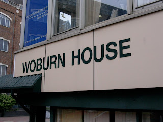
The images below are photographs me and my brother took of the existing building and proposed site.


Map of Area

Aerial Photograph

Aerial Photograph (Zoom)

I have carried out additional research into the area where this hotel is planned to be built. I have also looked at the proposed site and existing building using the internet and the google mapping system. It would probably help if I gave Google Earth a try, which will show the area in more detail and from ground level so as to get a more accurate sense of the environment.

I have already been to site personally to acquire an understanding of the location.

The address of the existing building upon the proposed site and new building project is: -

Woburn House
155 Falcon Road
Battersea
London
SW11 2PD

The existing building is an employment and recruitment company and job centre.


Plans & Elevations


The plan and elevation drawings below were all created by the architectural practice Husband & Carpenter. I shall be using these drawings for reference in order to help me construct a 3D model of the building (hotel)

PLAN DRAWINGS:

Ground Floor Plan

First Floor Plan

Second Floor Plan

Third Floor Plan

Fourth Floor Plan

Fifth Floor Plan

Sixth Floor Plan

Seventh Floor Plan

Roof Plan

ELEVATION DRAWINGS:

West Elevation
East Elevation
South Elevation
North Elevation


I have looked at the plans and elevations and me and my brother have begun to arrange the material, making sure all he reference drawings are to scale when applying image planes into Maya.

The building me and my brother are creating in Maya is currently in the middle of getting planning permission. The site is located on Falcon Lane near Clapham Junction, London.

The concept below is an image drawn by an architectural artist who works for the company.
This image demonstrates what the building exterior may look like.

Husband & Carpenter have indicated that the colour scheme for the exterior panel work of the hotel has changed since this concept was completed.